Renderings done with Keyshot 6/7 and Solidworks PhotoView 360. Credit to Keyshot for bowling and drill model, & credit to GrabCAD user "and" for T-Rex Model. All other models were created by me in Solidworks.
PhotoView 360
PhotoView 360
PhotoView 360
PhotoView 360
Keyshot 6
Keyshot 7
Keyshot 7
Keyshot 7
Keyshot 7
Keyshot 7
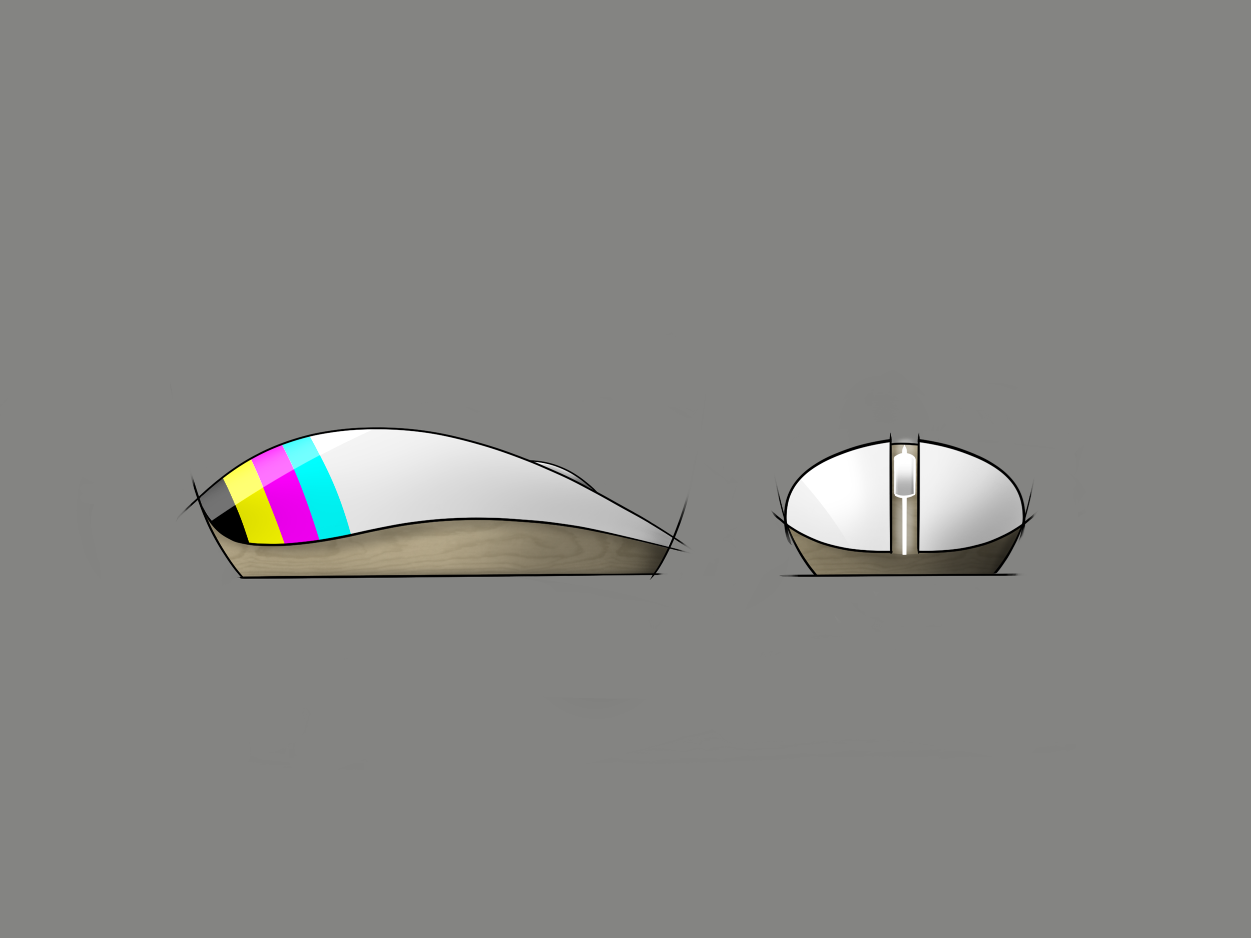
Digital sketches done with ProCreate for iPad Pro
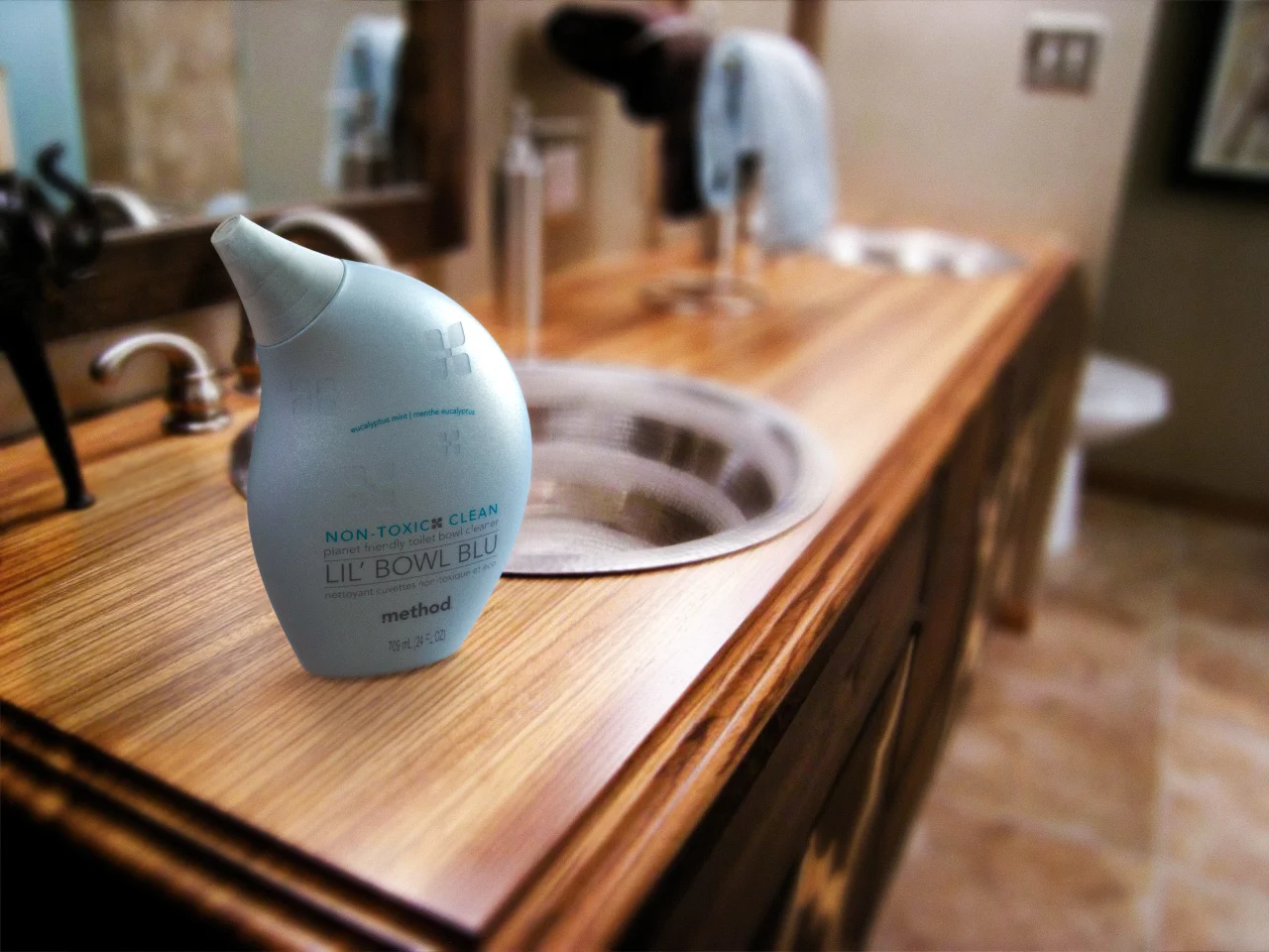
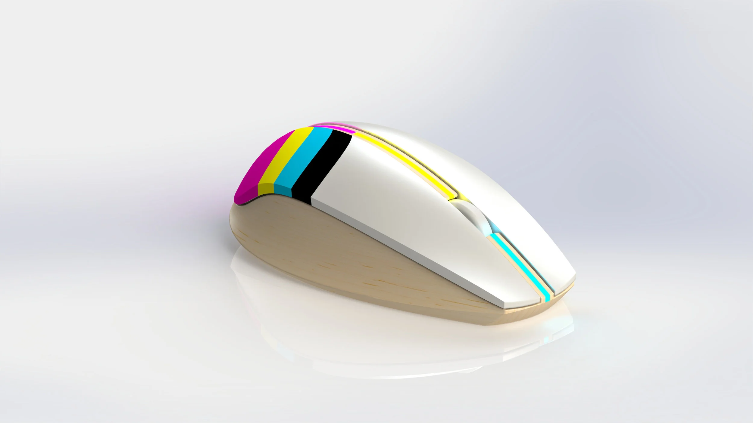
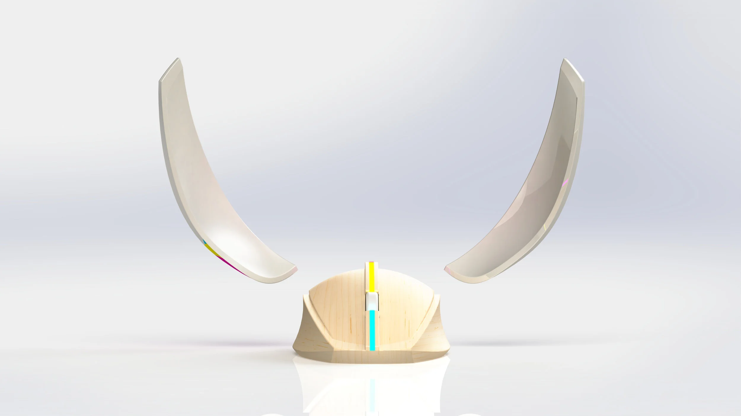
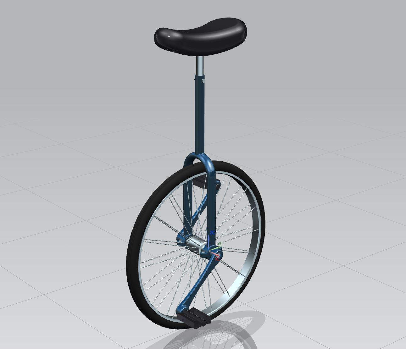
Mouse, detergent bottle, method bottle, and toothbrush done in Solidworks. Unicycle and pumpkin done in NX.
Designs created in Adobe Photoshop & Illustrator
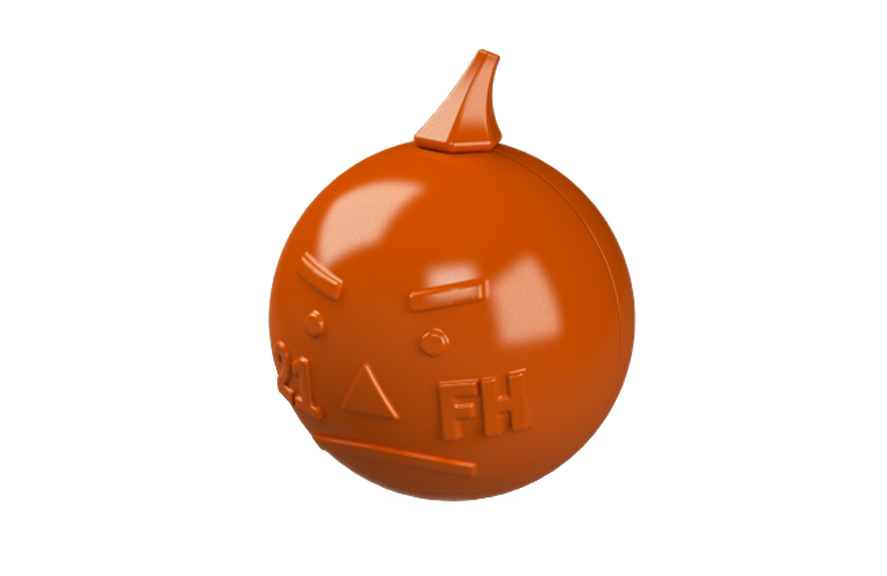
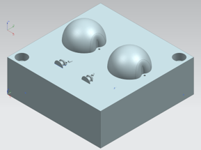
Over the course of ten weeks, my team was able to learn the process for creating an injection molded product of considerable complexity (including four parts that fit together using a combination of pin-and-hole interference fits and clearance fits). We used Siemens NX to create part and mold models, manufactured our molds using a CNC machine, and ran an injection molding production run of 127 parts. My roles included modeling the body of the pumpkin, creating the CAM operations required to create the mold, and helping oversee our production run.
Render of final product
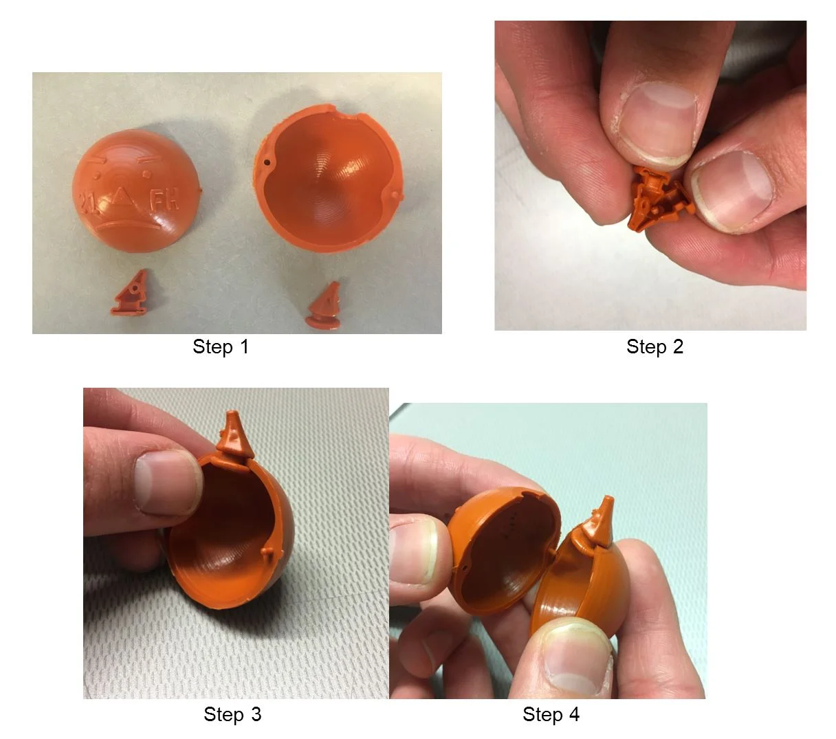
Assembly of final part
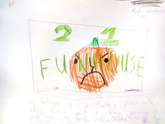
Inspiration drawing done by 4th Grade Student
Group with cavity mold
Mold Design in NX
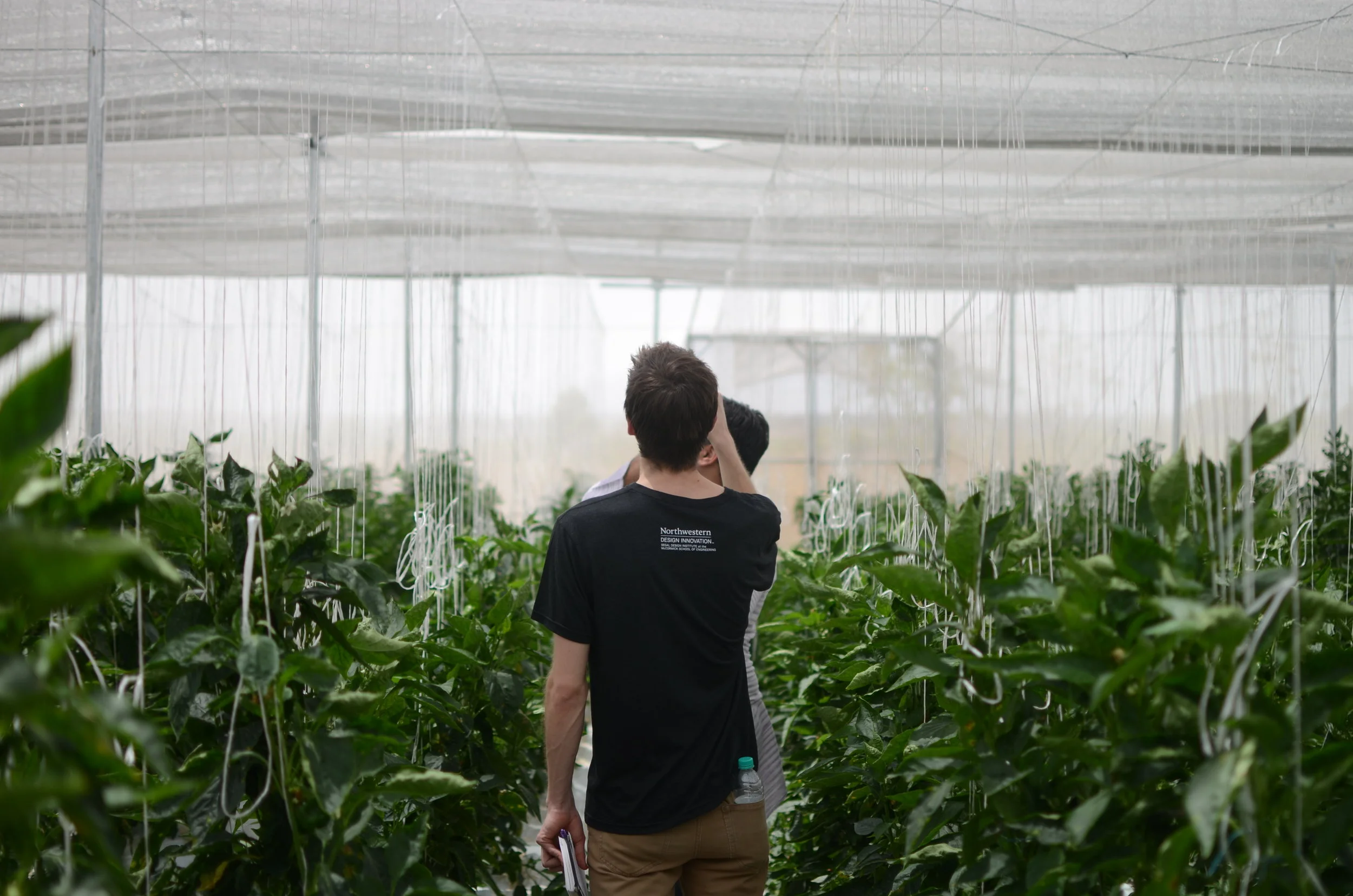
The goal of this 6 month project was to assist the organization Kheyti in achieving their goal of providing a cheap, DIY shadehouse to smallholder farmers in India.
Our 4 person team quickly realized that we needed to specialize in order to have the biggest impact for Kheyti. Therefore, we decided to focus on the foundation, and delivered a stake based foundation that was cheaper and easier to install than their current concrete solution.
We had the opportunity to travel to Hyderabad, India for a week in order to interview farmers, test our proposed solution, and meet with Agriplast, the greenhouse manufacturer working with Kheyti. This trip informed changes to our design, in order to deliver a solution that was helpful and feasible.
This project involved extensive testing, planning, research, prototyping and communication. These roles were shared among the team, but each team member had specific duties as well.
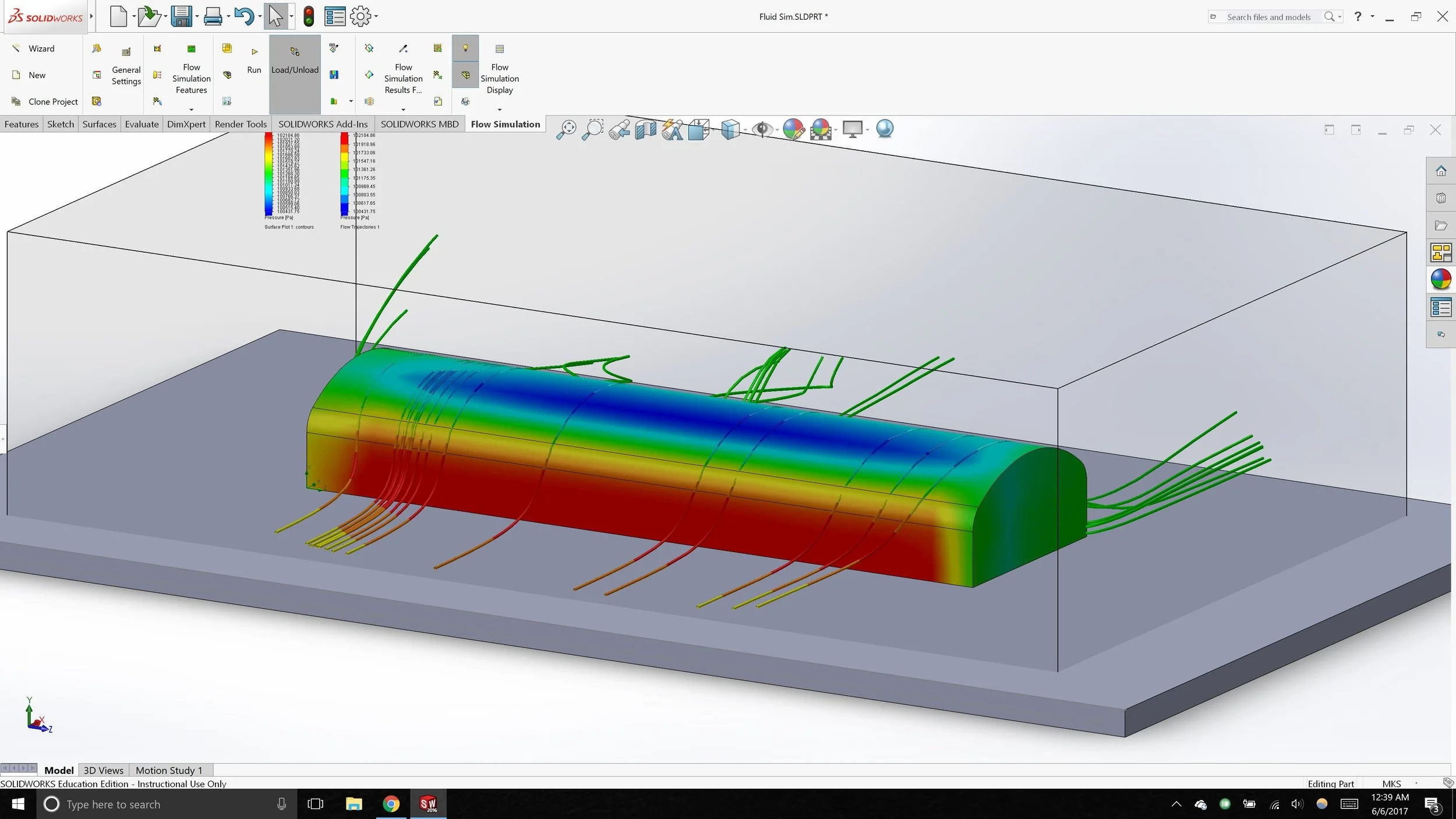
My main specialty role on the project was to handle the force analysis of our design, in order to inform and validate our final decisions. I did this through a combination of physical testing of the covering mesh's reaction to wind, fluid simulation through Solidworks of the wind forces imposed on the structure, and on paper analysis.
Our team had the opportunity to visit farmers in Hyderabad, India
Onsite testing of stake strength
Solidworks Flow Simulation used to estimate wind forces on structure
Component overview of proposed foundation
Final Render of proposed foundation
The goal of this project was to create three shaft, four gear transmission system to achieve a certain output given an input motor speed and power. Each team member designed one shaft and it’s corresponding gears and completed a bearing selection. All three shafts were then assembled into the full CAD assembly.
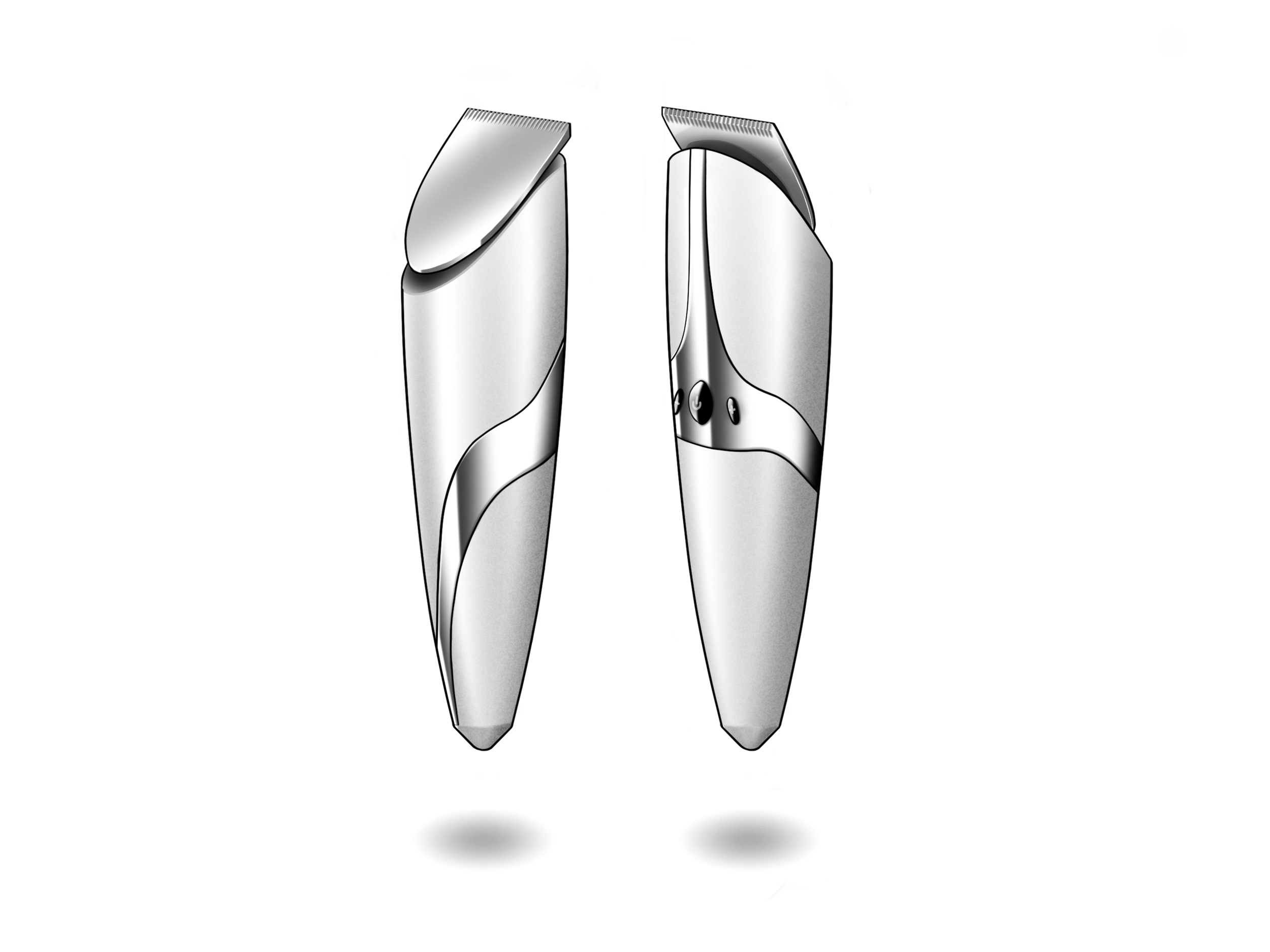
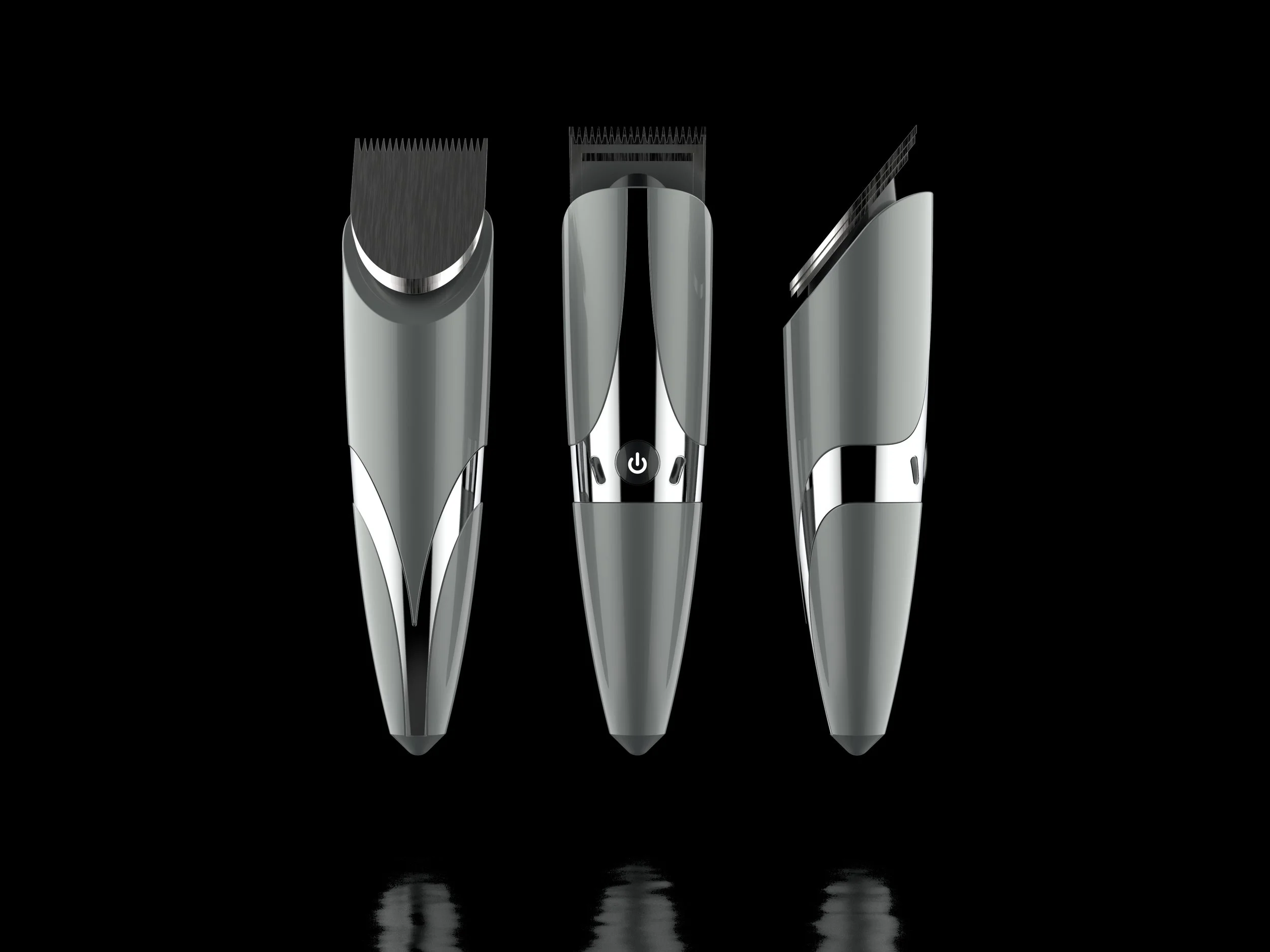
This exercise focused on the creation of a concept electric hair clipper. The project was taken from broad ideation to final concept renderings
Initial ideation. Concept 3 moves forwards
Concept 3 Variations. Variation 4 (from the left) moves forward
Variation 4 perspective view
Digital Sketch created with ProCreate for iPad Pro
Render created with Keyshot 7
Render created with Keyshot 7
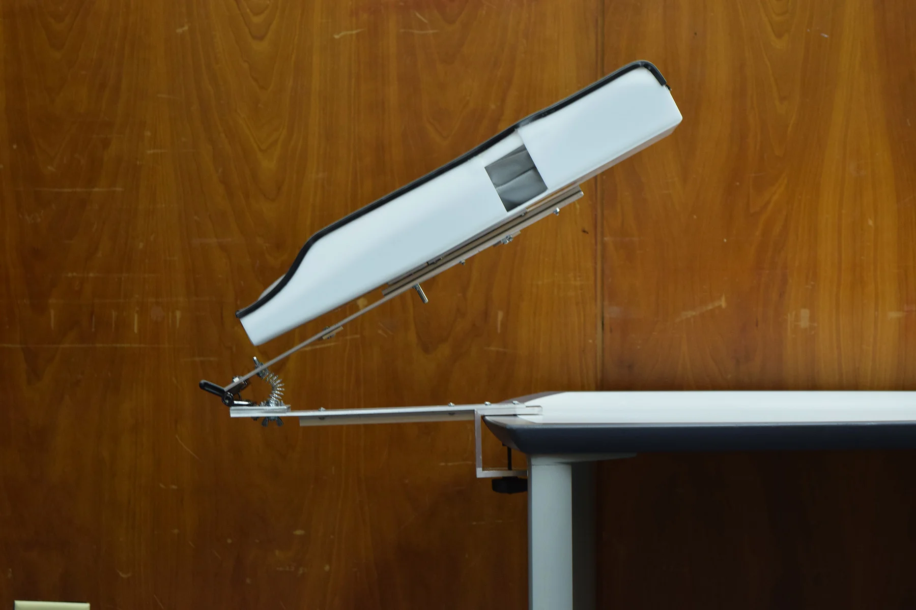
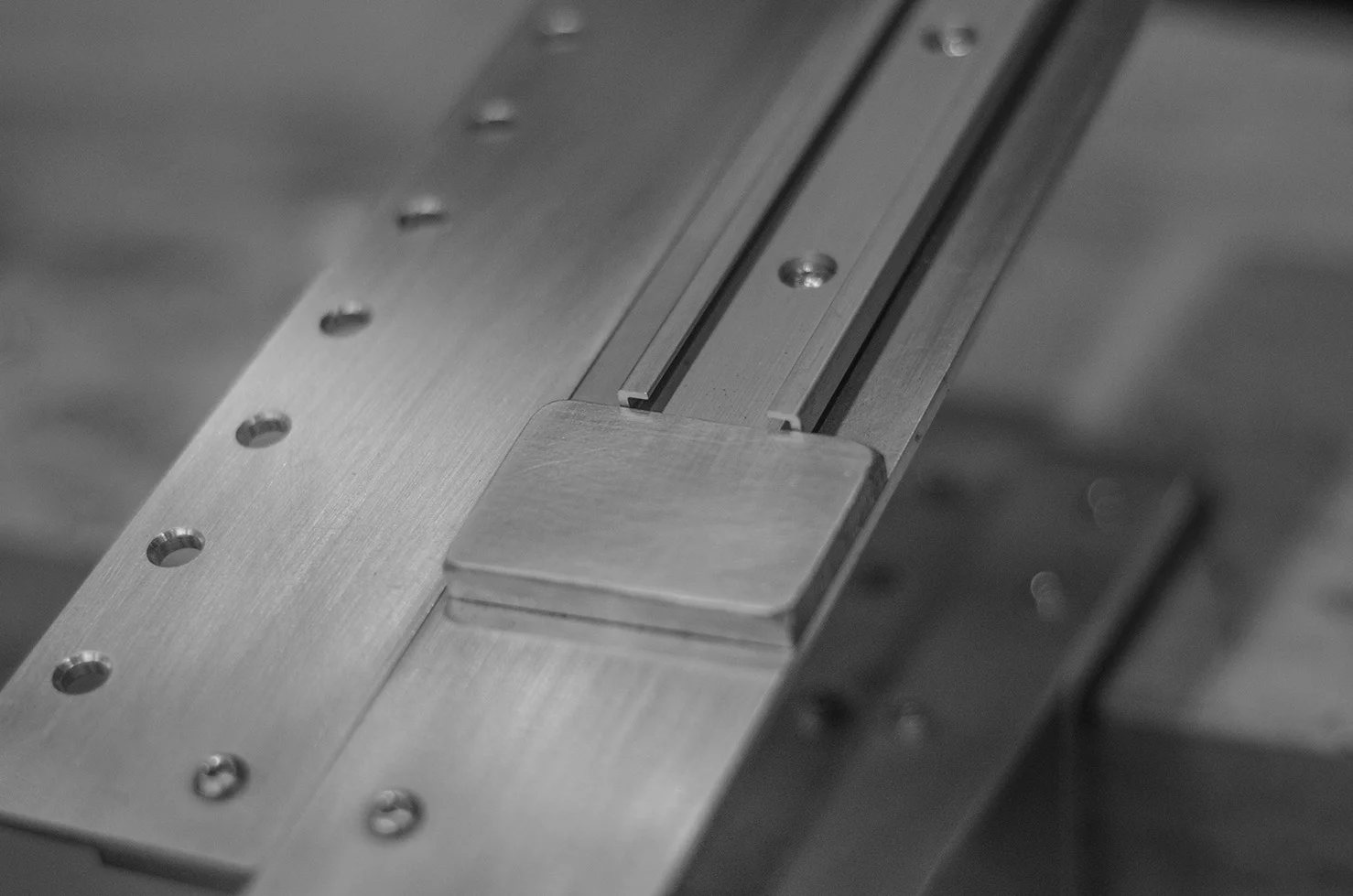
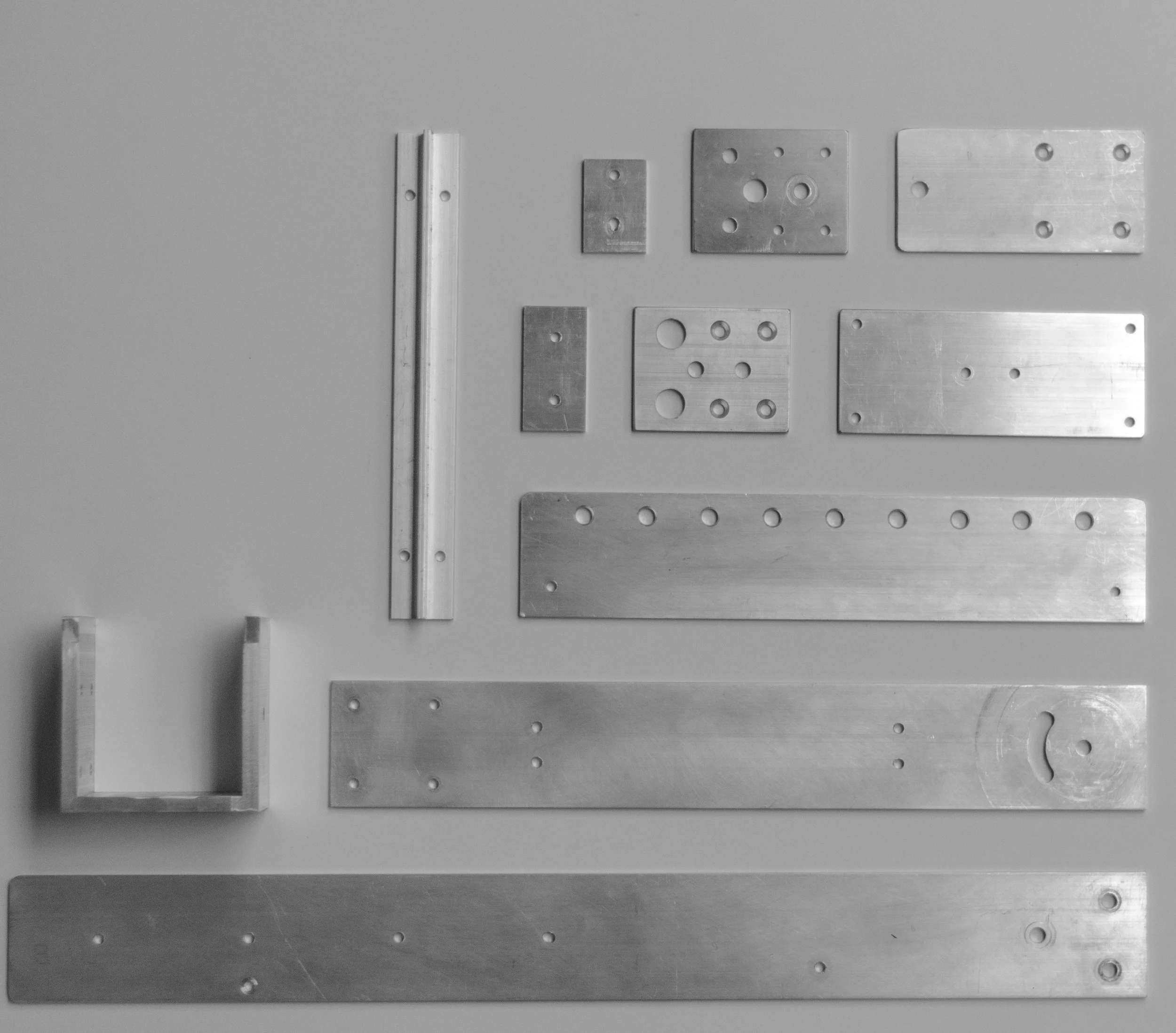
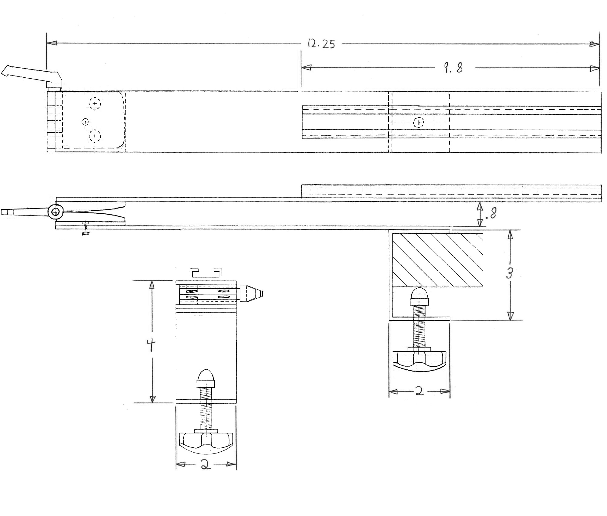
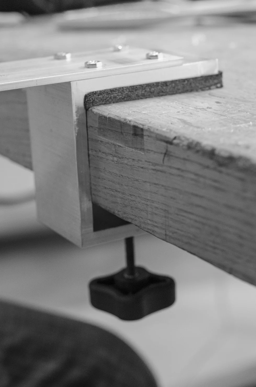
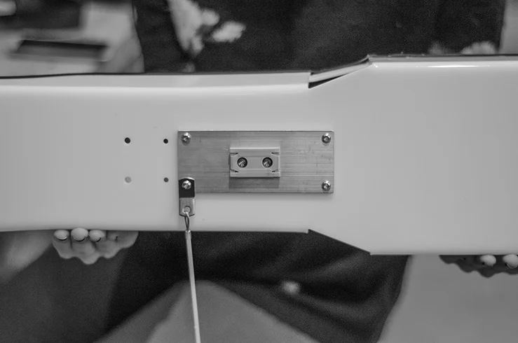
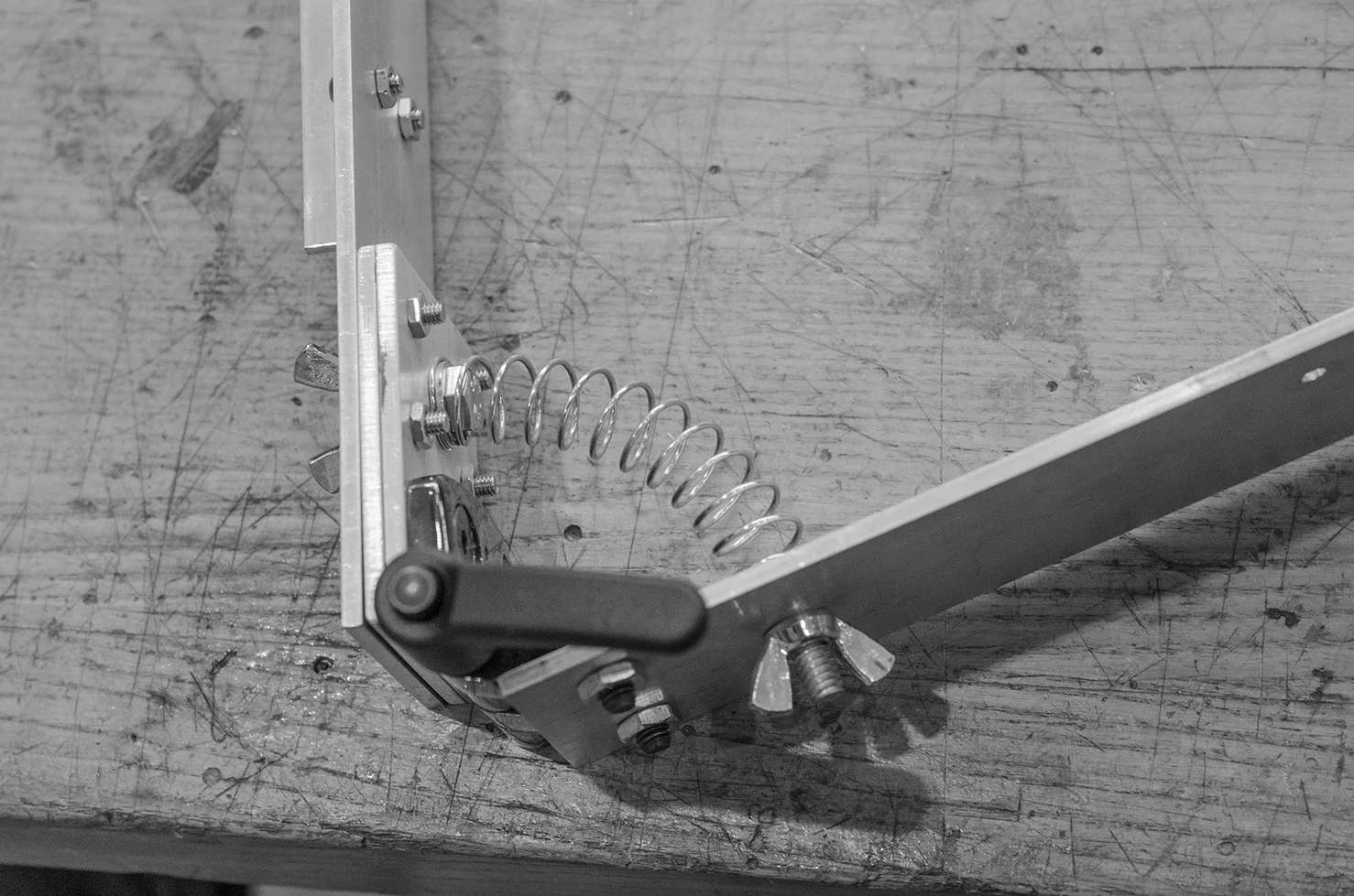
In collaboration with the Rehabilitation Institute in Chicago, I and a team of three other students designed and constructed a prototype arm positioning device for people with hemiplegia. Hemiplegia is a condition in which half of the body is paralyzed, and a common side effect is shoulder subluxation (partial or full dislocation). This can be prevented with a device that supports the arm, but the solutions were inadequate in many situations.
Our device, the 3DAPS, addressed specifically the lack of arm support systems available when seated at a table. The device clamps onto the table, and through a series of lockable motions, is able to move an arm into numerous positions. The device aims to prevent subluxation, reduce edema, and assist in the performance of rehabilitating stretches.
My role on the team encompassed the majority of the technical design and fabrication of the device. I performed 90% of the required machining, oversaw the design of the articulating portion of the device, completed the majority of required drawings, and designed/photographed the visuals required for the presentation of out project.
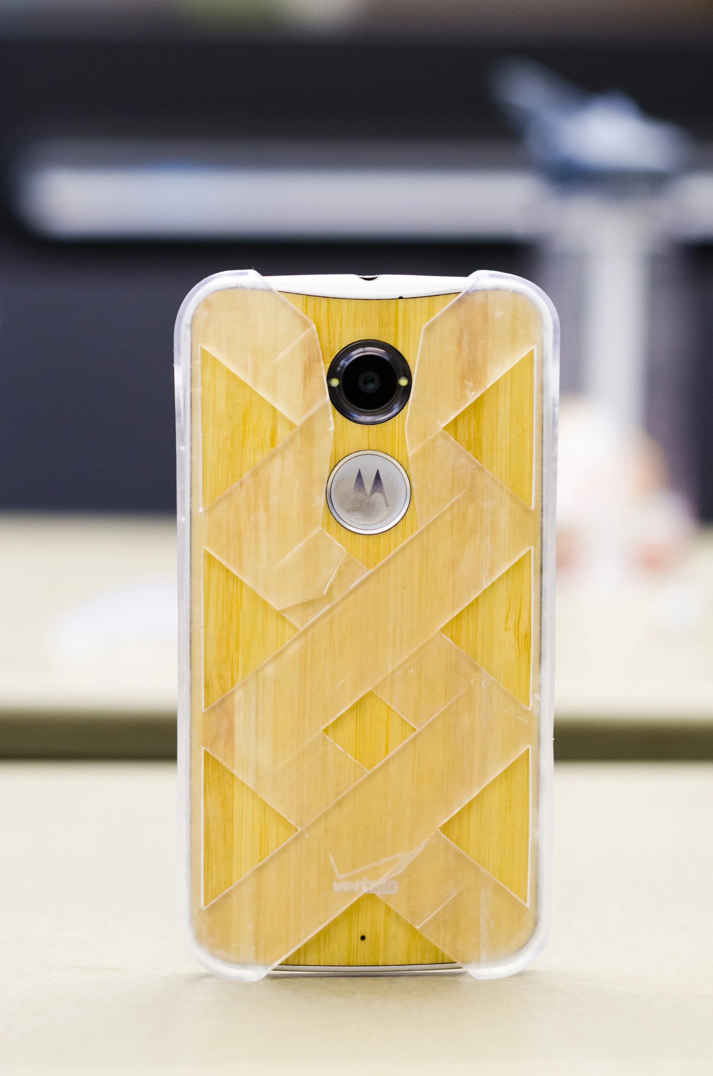
This project was focused on the design and creation of a Motorola Moto X (2014) phone case through the use of rapid prototyping (RP) technologies. In this case, a Formlabs Form2 printer was used to create each iteration. Three iterations were created in total, each improving some aspect of the last via user feedback. This user feedback was collected mainly with regards to how the phone was being held in the hand. It was found that there are three predominant methods of holding a phone, and the final iteration of the phone case improved the grip of each of these types through the use of ridges and negative space.
Most common phone-holding positions
All three phone case iterations
Final Iteration CAD Model
Final Phone Case
This project required teams to design and construct a two member system capable of withstanding 2,000 - 2,500N of upward applied load. In preparation for construction, an optimal design was calculated with regards to bracket geometry, stress analysis, weight, and cost considerations. This optimization started with the analysis of preliminary individual design and was then improved upon by utilizing MATLAB code to model how stress in the bracket changed based on changing certain parameters. The first iteration of the bracket was designed to fail by shearing of the connection point on the lower member at an applied load of 2,320 Newtons. All other theoretical resultant stresses were below the calculated thresholds of failure. A first round of testing to failure was conducted at this point to observe how the bracket performed under real-world conditions. This version bracket failed below its theoretical strength, due to holes drilled too close to bracket member edges, and an unforeseen bending moment at one of the two mounting points. These errors were corrected in the second iteration of the bracket. This second version failed in the desired mode and location, but again at a load below the desired amount due to an oversight of the load machine’s attachment bolt size. My role in the project was to assist in the fabrication of the bracket, as well as the analysis of the failure mode of the bracket to inform future versions.